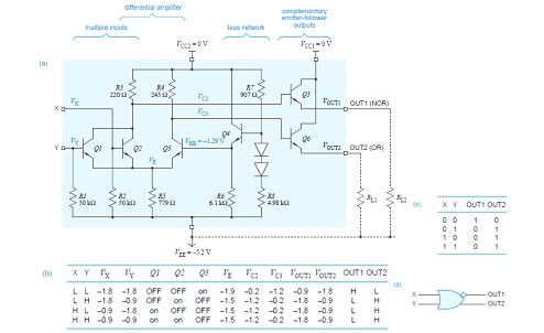
Ecl Nor Gate Circuit Diagram
Nor simple gate transistor level diagram transistors circuit schematic logic input electrical nand digital question stack Nor gate logic gates truth table output introduction its high technology inputs if Ecl gate nor circuit circuitlab description
VLSI Design: Emitter Coupled Logic
Nor gate electronics digital three shows wiki tutorials inputs keys bulb named switch circuit Nor gates tutorial Emitter-coupled logic
Ecl circuit nor simulator
Introduction to logic gates – projectiot123 esp32,raspberry pi,iot projectsEcl gate nor transistor working explain describe turned 8v corresponding obvious input then any very if high diagram Ecl gate nor logic emitter coupled dual fig learnabout electronics digitalVlsi design: emitter coupled logic.
Ecl gate nor logic bipolar input circuits chapter ppt powerpoint presentation microelectronic mcgraw variations circuit hill threeNor circuit gates basic Nor circuit logic two switches switch gates gate electrical schematicNor gate ecl input digital.

Digital electronics
Vlsi design: emitter coupled logicCircuit ecl diagram gate input nor Nor gates circuits tutorial gate digital electronicEmitter coupled ecl transistor ttl.
Emitter coupled logic (ecl)Ecl two input or/ nor gate 7.1 ecl or/nor gateEcl logic emitter coupled nor input.

Ecl output nor gate logic input seventeen chapter emitter follower stages figure ppt powerpoint presentation two
Logic gatesConversion of nor gate to basic gates Digital logicLogic coupled ecl emitter gate circuit nor vlsi table cml diagram 10h 10k families.
Ecl nor/orEmitter coupled logic gate nor Or/nor gate of emitter coupled logicHow logic gates work.

Circuit diagram of the basic fan-out of one ecl or-nor gate. one input
What is nor gateDescribe a basic ecl nor gate and explain its working in short with the Logic ecl nor gate table truth emitter coupled circuit diagram 10k input fig two.
.


Conversion of NOR gate to Basic gates

Digital Electronics | Digital Techniques | ECL 2 input OR/NOR Gate

OR/NOR Gate of Emitter Coupled Logic - YouTube
7.1 ECL OR/NOR gate - CircuitLab

Introduction to logic gates – projectiot123 esp32,raspberry pi,iot projects
Circuit diagram of the basic fan-out of one ECL OR-NOR gate. One input

VLSI Design: Emitter Coupled Logic

VLSI Design: Emitter Coupled Logic